

Summary
A step-by-step Guide with photographs and tips on how we setup and align a telescope on a go-to Equatorial mount, for tracking celestial objects.
Note: All images in this post are © STAC 2023
Equipment
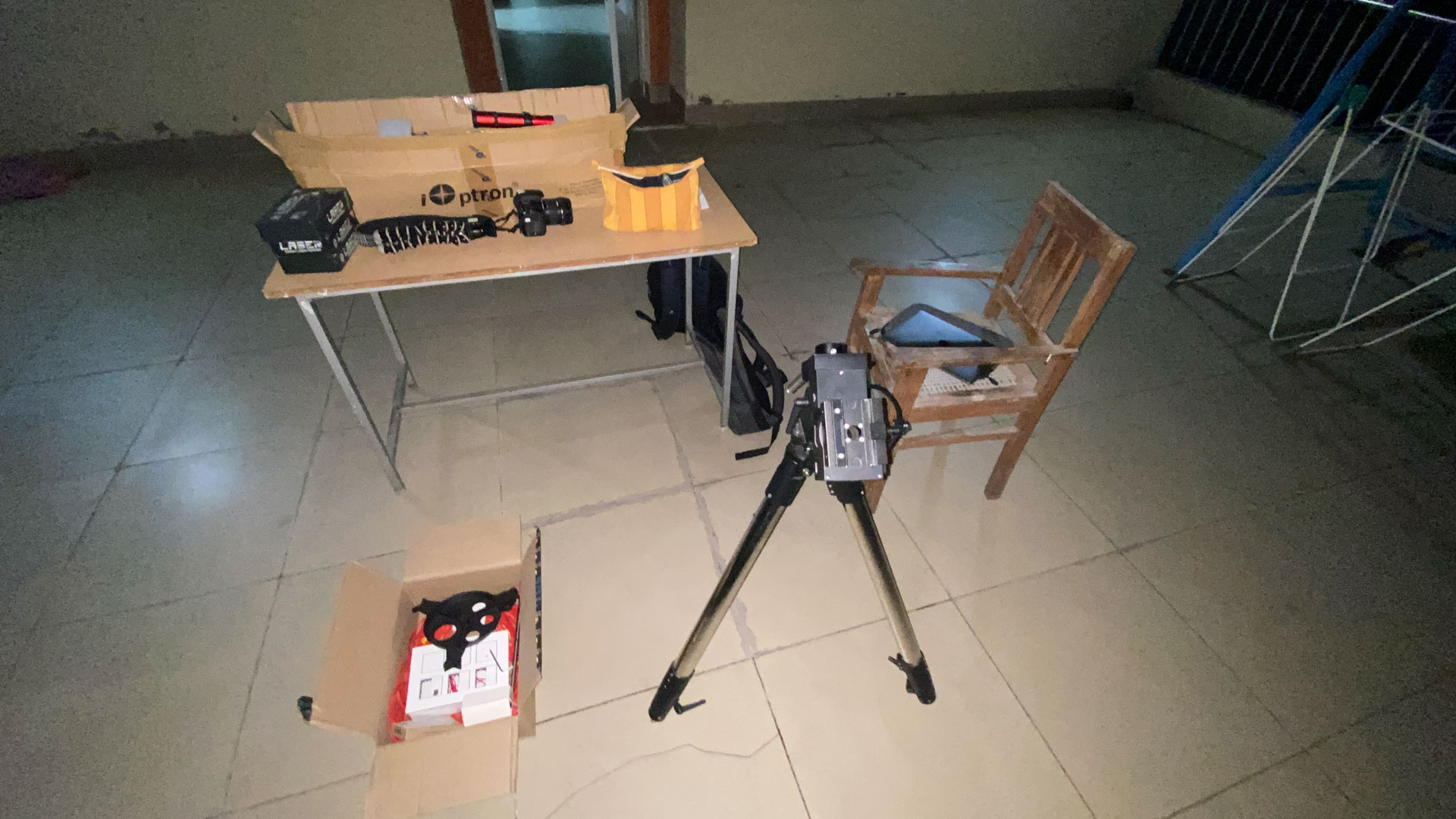
The main gear used in our setup is :
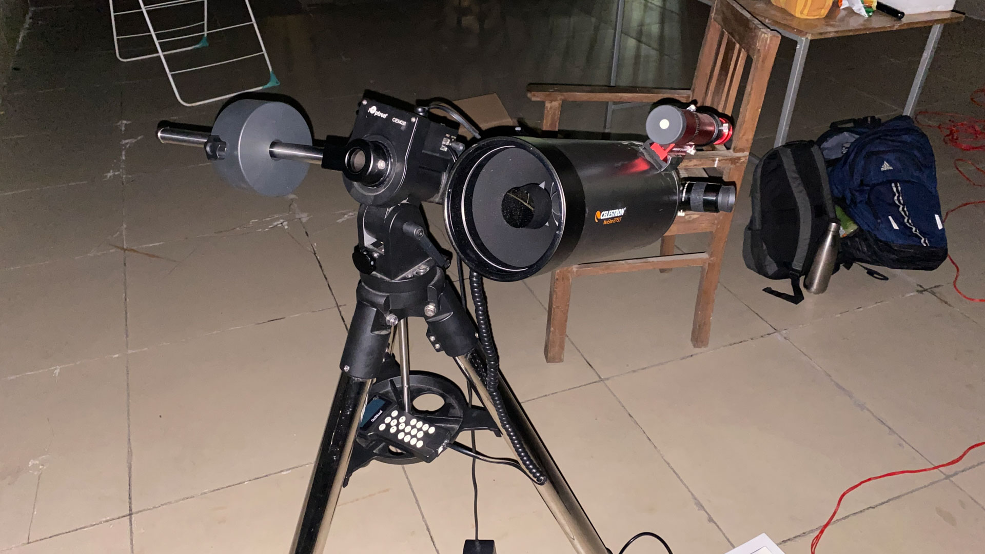
- Telescope : Celestron 127 SLT Maksutov Cassegrain
- Mount : iOptron CEM26 GoTo Equatorial
Alternatively, the club also has a Celestron Astromaster 130EQ Newtonian on a non-computerised equatorial mount with motor drive.
Other equipment checklist :
- Eyepieces : Atleast 1 wide-field (> 20 mm), and optionally 1 narrow (< 10 mm) and/or 2x barlow
- Telescope Counterweight : 1 x 4.5kg
- AC Power Extension Cord and RJ45 cables
- Laser to point to stars etc
- Lens Cleaning Kit to wipe off dew and dust.
This is sufficient for the setup described in this post (Part 1), which will allow manual observation. For imaging, more equipment and software is necessary as described in Part 2.
Preparation
Choosing a Time and Location
Pick an area that has:
- A power outlet nearby, within range of the AC extension cord used to power the mount. In order to setup the telescope at a remote campsite, we will need to purchase a power bank instead.
- Sufficient field of view of the sky, and minimal ambient light pollution.
- Stable, flat ground so that it is easier to adjust the tripod.
To find a suitable time:
- For cloud cover forecast, clearoutside.com and timeanddate.com have often been reliable for dates within 1 week.
- For planetary observations, moonlight is not a major problem, however deep sky targets like galaxies are almost invisible when the illumination is > 50%, especially in directions closer to the moon.
- Dew can cause lots of difficulty, so nights with lesser humidity are easier to work in. Keep wiping off wet surfaces and ensure that the electronics stay dry. We can consider purchasing dew heaters in the future.
Collimation
If the optical elements of the telescope are not correctly aligned, the images produced can be very distorted or unclear. Cassegrain telescopes (such as the one we are using in this session) typically don’t need regular alignment, and it should be okay to use directly.
Additionally, align the finder scope on the telescope as parallel to the main tube as possible, if you will be using it. This tends to easily get shaken out of place during transportation. By pointing the telescope at an easily recognisable object (E.g. - moon, bright planet or star, Pleiades, etc) check that the same is visible within the finder view or guide cam feed.
However in case a Newtonian reflector (like the club’s Celestron Astromaster 130EQ) is being used, check the alignment of the primary and secondary mirrors - the axes are often titled, especially due to being shaken after transporting. It is also easy enough to collimate manually. Adjust the orientation of the primary mirror using the 3 cylindrical metallic thumbscrews on the back of the telescope, and the secondary using a screwdriver to turn the 3 small plus shaped screws on the circumference of the secondary mirror mount inside the tube. All reflections and borders of the mirrors/tube should be concentric circles when looking into the telescope without an eyepiece. Use a collimation cap or laser collimator to avoid parallax error while looking for any offset. Refer to a proper collimation guide for details.
Mount Setup
Tripod Setup
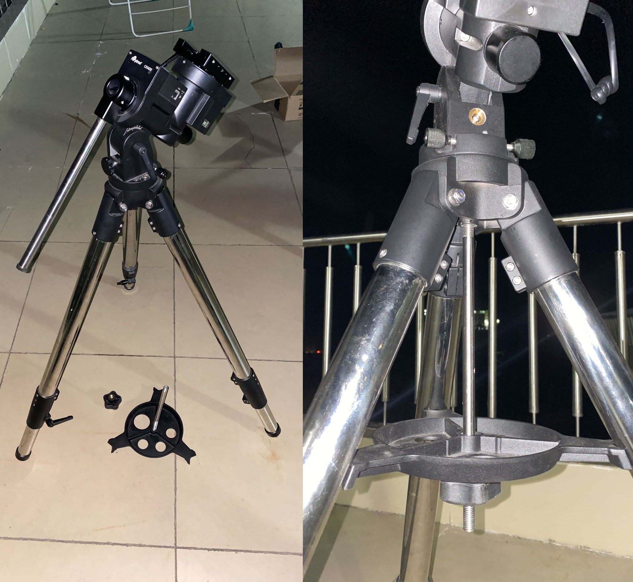
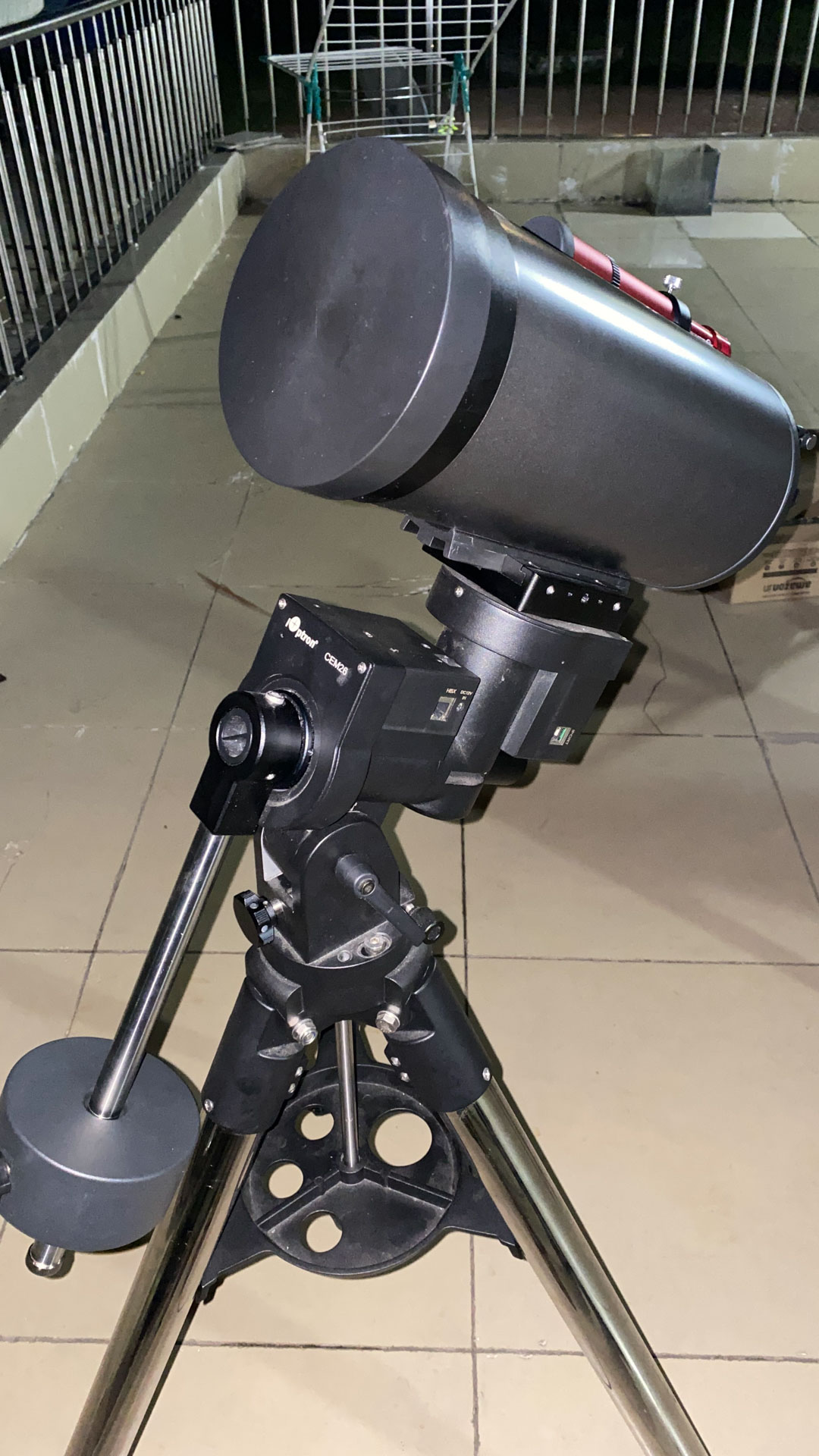
Open the tripod legs completely and place it on the ground stably. If the motorised mount head was removed from the tripod, fix it onto the tripod by aligning the steel rod and 2 slots for the screws correctly as shown in the image below. Tighten the screws and make sure that the mount is securely fixed.

Orient the stand so that it is roughly facing north, as shown below (since campus is in the Northern hemisphere, we will need to align it with the North Celestial Pole).

(Optional) Then, fix the accessory tray between the legs using the steel rod with screw threads on both ends (the rod with threads only on 1 end is for the counterweight) and the cap, as shown below.
Adjust the length of the legs precisely so that the base of the mount is perfectly horizontal. The bubble spirit level on the mount helps to show any tilt. Check this from all directions to avoid parallax error.

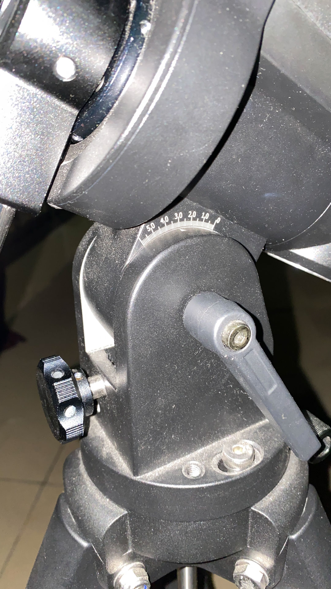
Then, adjust the latitude axis on the mount so that it is tilted at the latitude equal to the observing site’s location. For IIT Mandi campus, this is around 31.8°N and doesn’t need to be changed afterwards.
Use the lever shown in the photo below to tighten/loosen the axis, and the knob in front to make fine adjustments.
We will align the tripod more precisely in the Polar Alignment Section in case it shakes during balancing.
Telescope Attachment
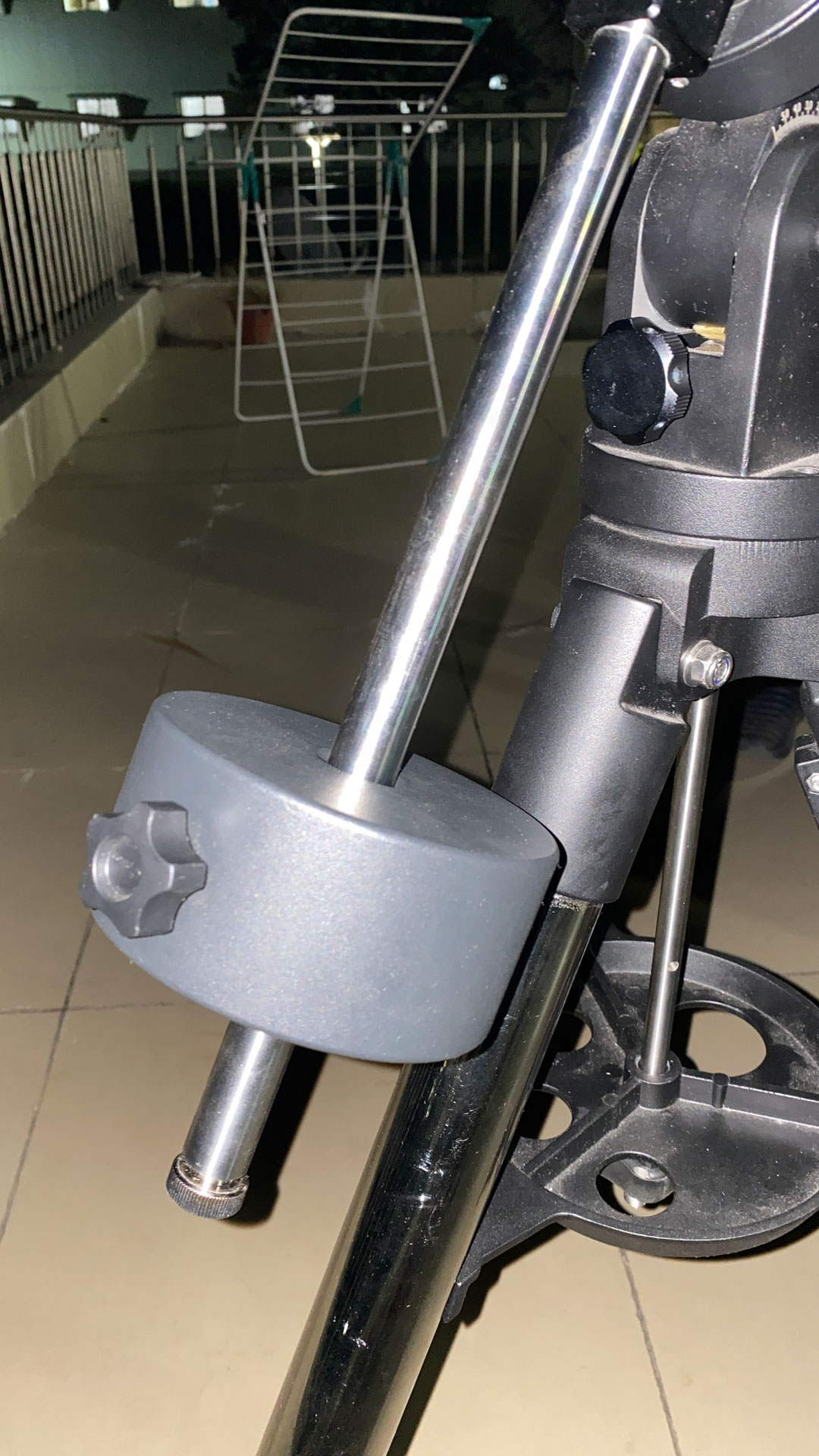
Before attaching the telescope, slide the counterweights onto the counterweight rod at the front of the mount, as shown below. The cap at the end of the rod needs to be unscrewed to add/remove the weight. For now, keep the weight towards the end of the rod, far from the mount head. Ensure that everything is tightly fixed in place so that there is no risk of the weight or rod falling off later.
Next, loosen the screw on the telescope Dovetail Slider at the top of the mount, and slide the telescope into place from the front as shown below. Then tighten the screw completely to fix it in place.
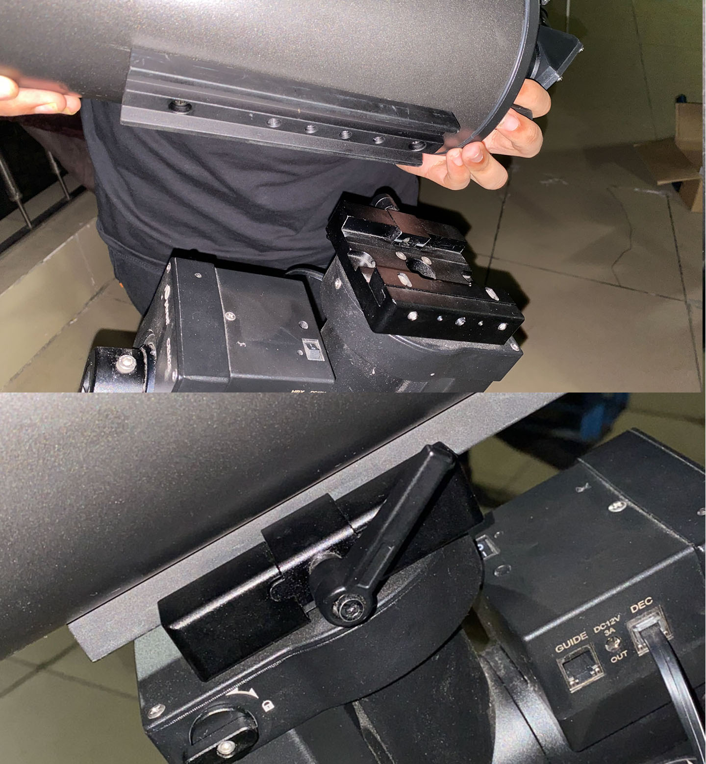
The front of the telescope would point upwards / Northwards / to the front of the mount.
Balancing
Balancing is an important step that involves shifting the center of mass of the telescope to a point over the tripod, so that the setup can stand still when unlocked, without swinging or falling to one side. This way there is also no net torque that the motor has to constantly apply to hold it in a stable position.
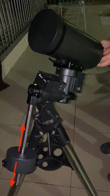
RA Axis
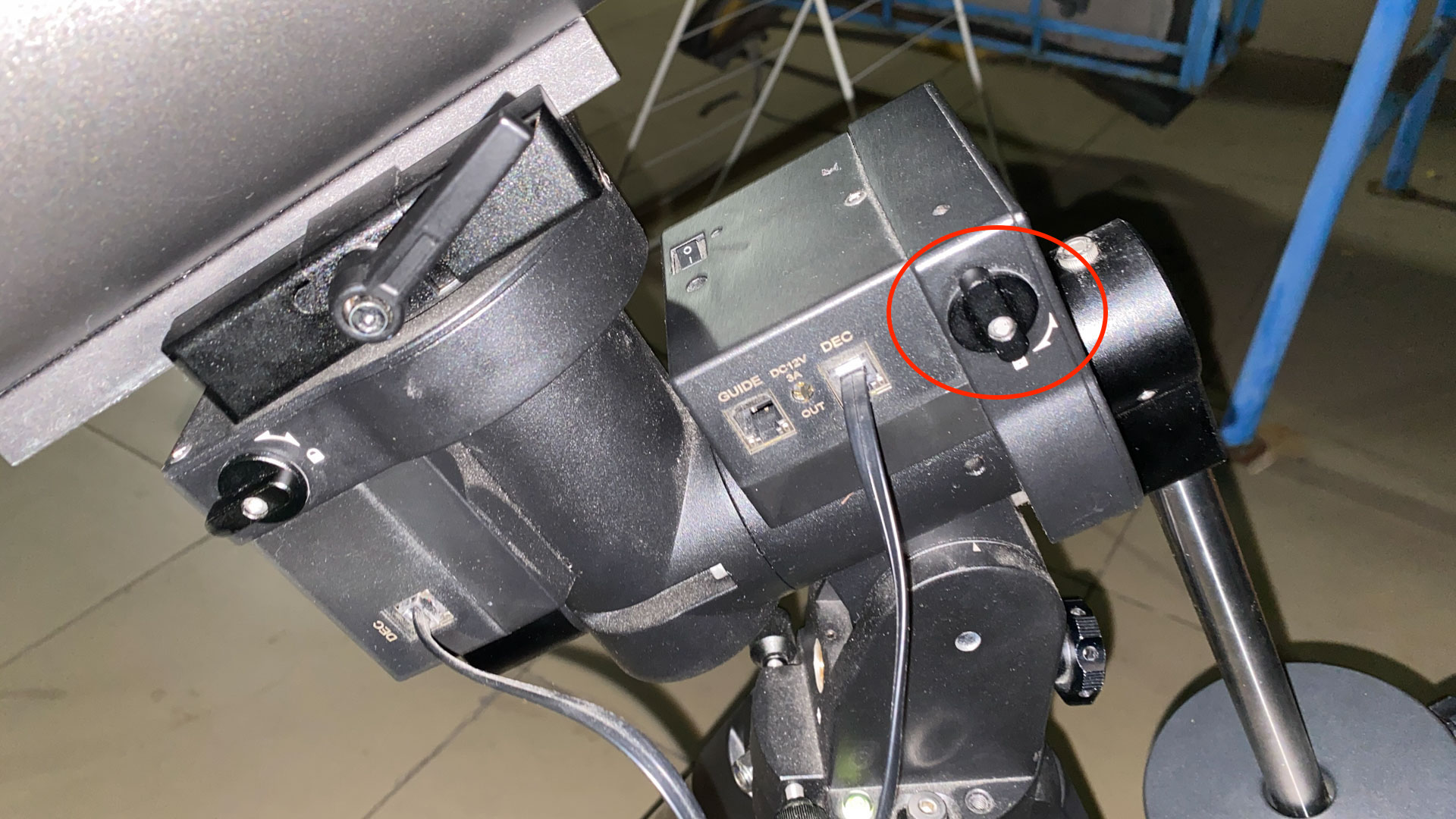
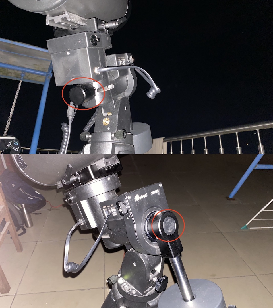
Around this axis, the telescope rotates clockwise/anticlockwise, or, east/west following the rising/setting motion of the stars in circles. It is parallel to the polar axis. To move freely around this axis, use the RA unlock switch near the front of the mount as shown in the figure below. Hold the telescope carefully while turning the switch so that it doesn’t suddenly fall over when unlocked!
Allow the telescope to slowly swing when unlocked. Observe whether the telescope tube tends to fall down or up. Lock the mount again, then loosen the counterweight and shift it lower down or further up on the rod respectively, to distribute the weight. Tighten the counterweight and allow the telescope tube to swing again.
Repeat until it is evenly balanced and can stay still at any angle, upwards or sideways, without falling. In case it seems “asymetrically” balanced, where it is stable at any angle on one side, but falls on the other side, refer to the Third axis balancing below.
If the counterweight needs to be shifted so low that it touches or gets stuck against the tripod legs, replace it with a narrower weight, or, add another heavier weight so that both can provide the same torque from closer to the pivot. Ensure that the setup can swing freely, else the motor may get damaged if the counterweight rod gets stuck in front of one of the tripod legs.
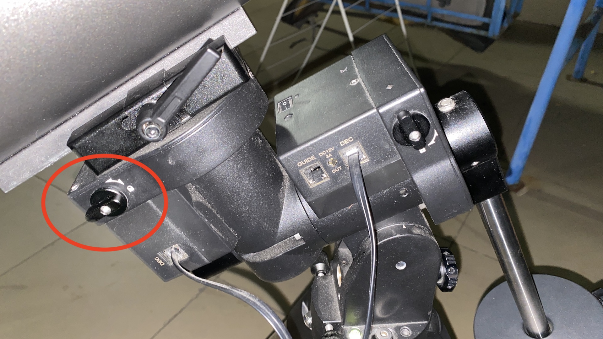
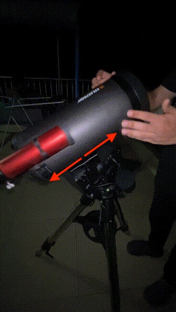
Dec Axis
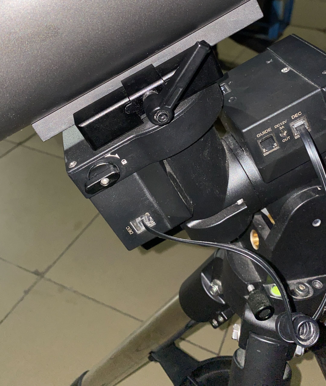
Around this axis, the telescope moves linearly from north to south, or, pointing from the front of the mount to back. It is parallel to the axis of the counterweight rod (perpendicular to the polar axis). Use the Dec unlock switch near the back of the mount as shown in the figure below. Again remember to be careful that the tube doesn’t swing suddenly and topple when unlocking.
Allow the telescope to slowly swing when unlocked. Observe whether the front end or the back of the Optical Tube Assembly (OTA) tends to fall downwards. Lock the axis again, then loosen the telescope tube in the Dovetail slider and slide it backward or forward respectively, to distribute the weight. Tighten the Dovetail slider lever before allowing the OTA to swing again.
Repeat until it is evenly balanced and can stay still at any angle, forwards or sideways, without falling. In case it seems “asymetrically” balanced, where it is stable at any angle on one side, but falls on the other side, refer to the Third axis balancing below.
Third Axis
This axis is the one through the OTA, and is the direction in which the telescope points to the sky, hence it is kept fixed because rotation around this axis only changes the orientation of the image in the eyepiece and not the point in the sky itself.
The OTA is not perfectly symmetrical around this axis - while the telescope tube is cylindrical - the finder scope (and in the case of Newtonians, also the eyepiece) that are on one side of the tube break the symmetry. Due to this, it may be difficult to properly balance the setup on the RA/Dec axes, and the symmetry needs to be corrected.
Typically this can be done by clipping extra weight onto one side of the telescope tube or the counterweight rod, opposite from the parts such as the finderscope that are causing asymmetry. We haven’t currently purchased any dedicated clips or weights for this purpose. Additionally, for an OTA such as our Astromaster 130EQ which is mounted using a Ring Clamp instead of a Dovetail slider, you can rotate the OTA itself about this axis to make the Finder Scope and Eyepiece vertically symmetrical and approximately balance the setup.
Misc Notes about Balancing:
- In case it is not possible to perfectly balance the telescope, a small non-zero torque on either axis is okay and won’t strain the motors too much. In this case, prefer to keep the slight imbalance on the RA+Third axes so that it is “east heavy”, i.e. - depending on which direction you will point the telescope to observe in, keep the end (OTA or the counterweight) that is on the East side (left side when looking at the mount from front/North) heavier.
- Keep in mind that when attaching other equipment (such as heavy cameras) at a later stage, the mount may need re-balancing again.
GoTo Tracker Initialisation
Power and Cables
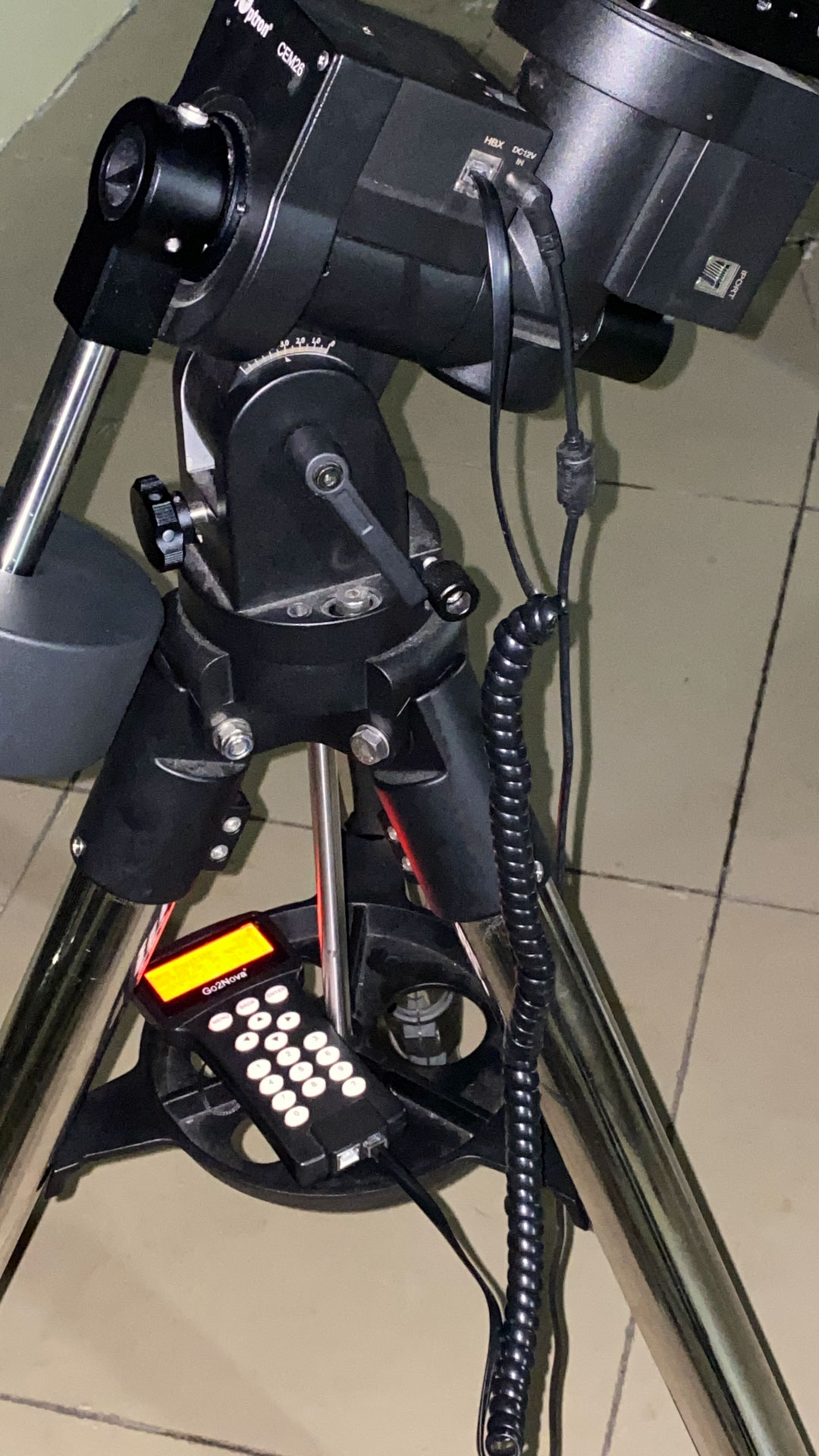
There are 3 cables used by the GoTo mount - 1 short & 1 long coiled RJ45 (ethernet-type) cable, and the power cable.
Connect the short RJ45 cable between both DEC ports on the mount as shown.
Use the long RJ45 cable to connect the GoTo controller to the HBX port on the mount as shown.
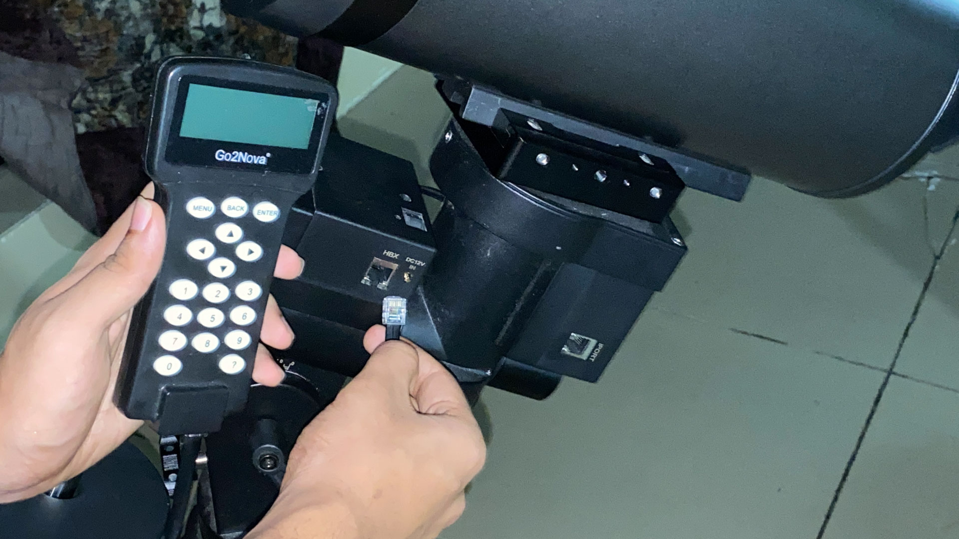
Connect the Power adapter to a regular AC source and the DC 12V IN port on the mount. Switch on the source and also the On/Off switch on the mount (above the DC IN port). If properly powered, the red LED on the mount and also the controller LCD panel will light up.

When the controller is first powered on, the iOptron logo appears on the LCD screen and then the menu. If you see any error message or the LCD does not light up or it flickers, check the power source and connections. Ensure that the power supply is stable and at a steady voltage to avoid damage.
Switching off or losing power will erase all the calibration data that is stored and you will have to repeat all the next alignment steps again.
Observing Site Data
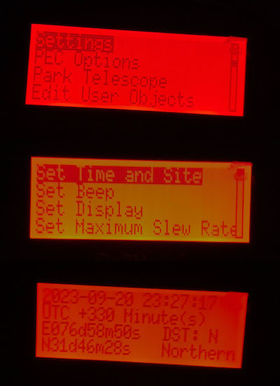
Press the MENU button at any time to display the menu that is also shown after the controller powers on. Use the up/down arrow keys to scroll to the Settings in the menu, and press ENTER. Next, enter Set Time and Site, and fill in all the details. Navigate between the fields using the arrow keys to fill values and press ENTER to save all at once.
- Current Local Date and Time. This should ideally be accurate to within ~1-2 seconds, so it’s helpful to enter a value for a minute later, fill all the fields and then, by watching a clock such as on timeanddate.com (or phone/laptop clock if you are sure that it is accurate), save it at the right moment.
- Timezone UTC offset. This is
+0530for Mandi campus (India). - Observing Site Latitude and Longitude. This should also ideally be accurate to within a few arcseconds. The value is
31°46'26" N 76°59'05" Efor Cricket ground, South campus. Add0°0'30"both N and E for Fountain area, North Campus. (Fun fact: The 77°00’00” E meridian passes through S11 / new SAC building, North Campus). - Hemisphere. Northern (N) for IIT Mandi. This defines the RA tracking to be around the North Celestial pole (Pole Star) instead of SCP.
Press ENTER to save all the data, including the time, and return to the Menu screen.
Polar Alignment
For this stage, you will need a torch light and optionally the help of another person.
Zero Position
Check that both the RA and Dec axes are aligned with the mount and locked so that the telescope also faces the front of the mount. After you adjusted the tripod and latitude as described in the section above, the OTA should point towards the pole star when the mount is in this position (see again this image). This is known as the Zero Position.
Scroll to Zero Position at the end of the controller Menu, Enter, and then enter Set Zero Position. You can now press back to return to the menu. At any later point of time, using Goto Zero Position will turn the axes back to this position so that you can re-adjust alignment or unlock the mount axes.
Pole Star Finder
Remove the caps of the Polar Alignment Scope that is the finder scope embedded in the RA axis of the mount.
Look into the back of the polar scope and check if Polaris is visible (we are aligning with the North Pole Star for the Northern Hemisphere). In case the tripod alignment with a compass was accurate and the latitude is correct, it should be visible.
If not, adjust the tripod itself so that Polaris appears roughly in the center of the view. Shift all tripod legs on the ground to rotate it, and extend/retract the front leg to move the mount up/down. Ensure that the spirit level still shows that the base of the mount is horizontal, even if the ground is uneven. This way, the tripod is pointing exactly north.
Polaris is a fairly bright star and should be easily recognisable, but you can also shine a laser through the polar scope or exactly parallel to the RA axis to check how far away the tripod is pointing.

Look through the polar scope while shining a light directly in from the front, and you will see the dial as in the image below.
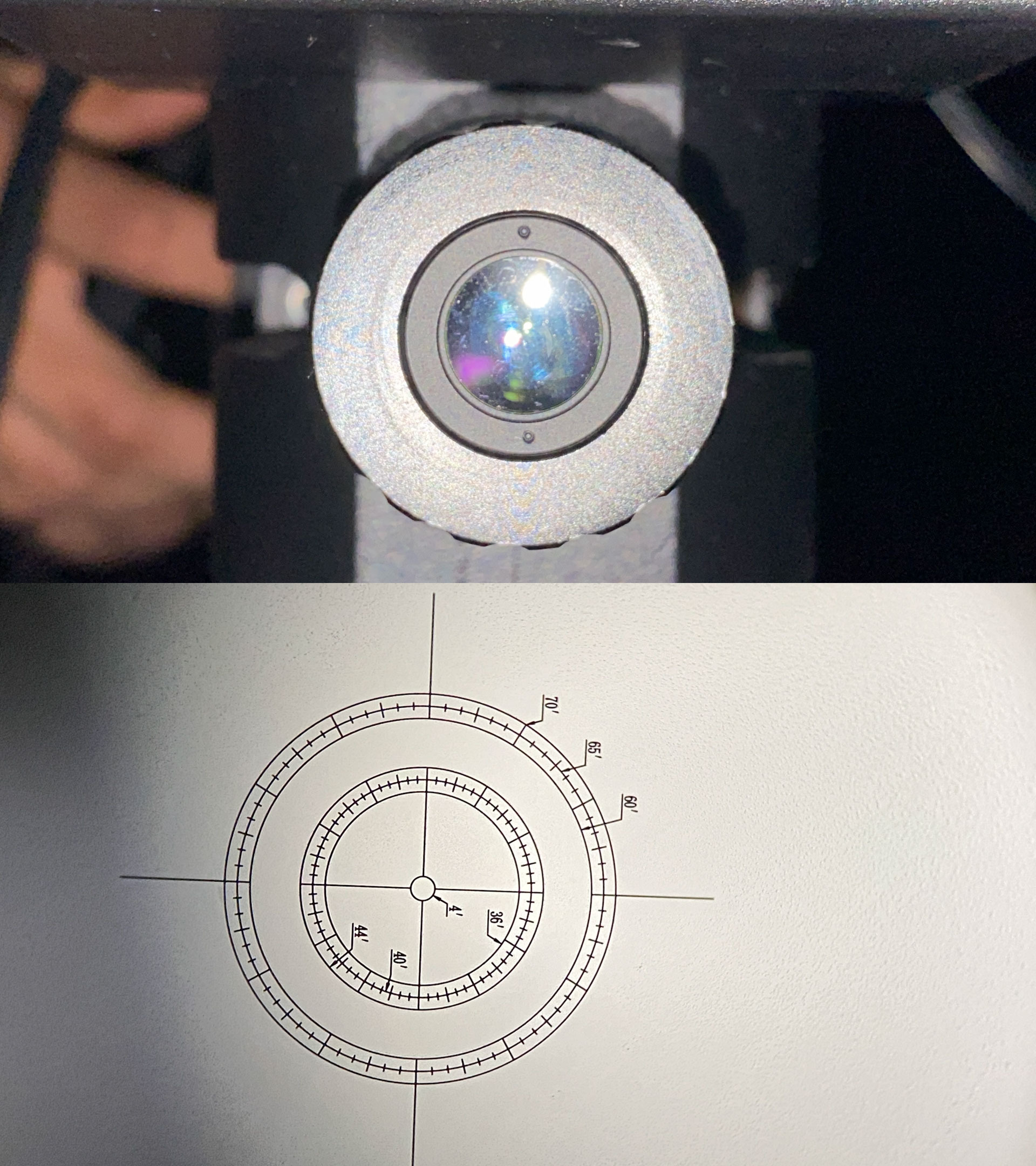
Unlock the RA axis of the mount and turn the telescope around 90° left so that the numbers on the dial are the right way up. This way, the dial is vertical and the markings can be compared to those on a 12-hour clock face, with circles showing radii in arc-minutes also drawn.
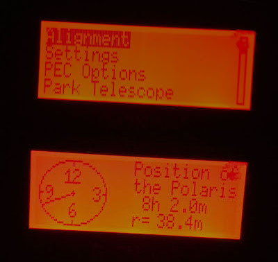
In the controller menu, go to Alignment > Pole Star Alignment and press ENTER. You will see a dial with the clock time and radius value displayed, as in the image.
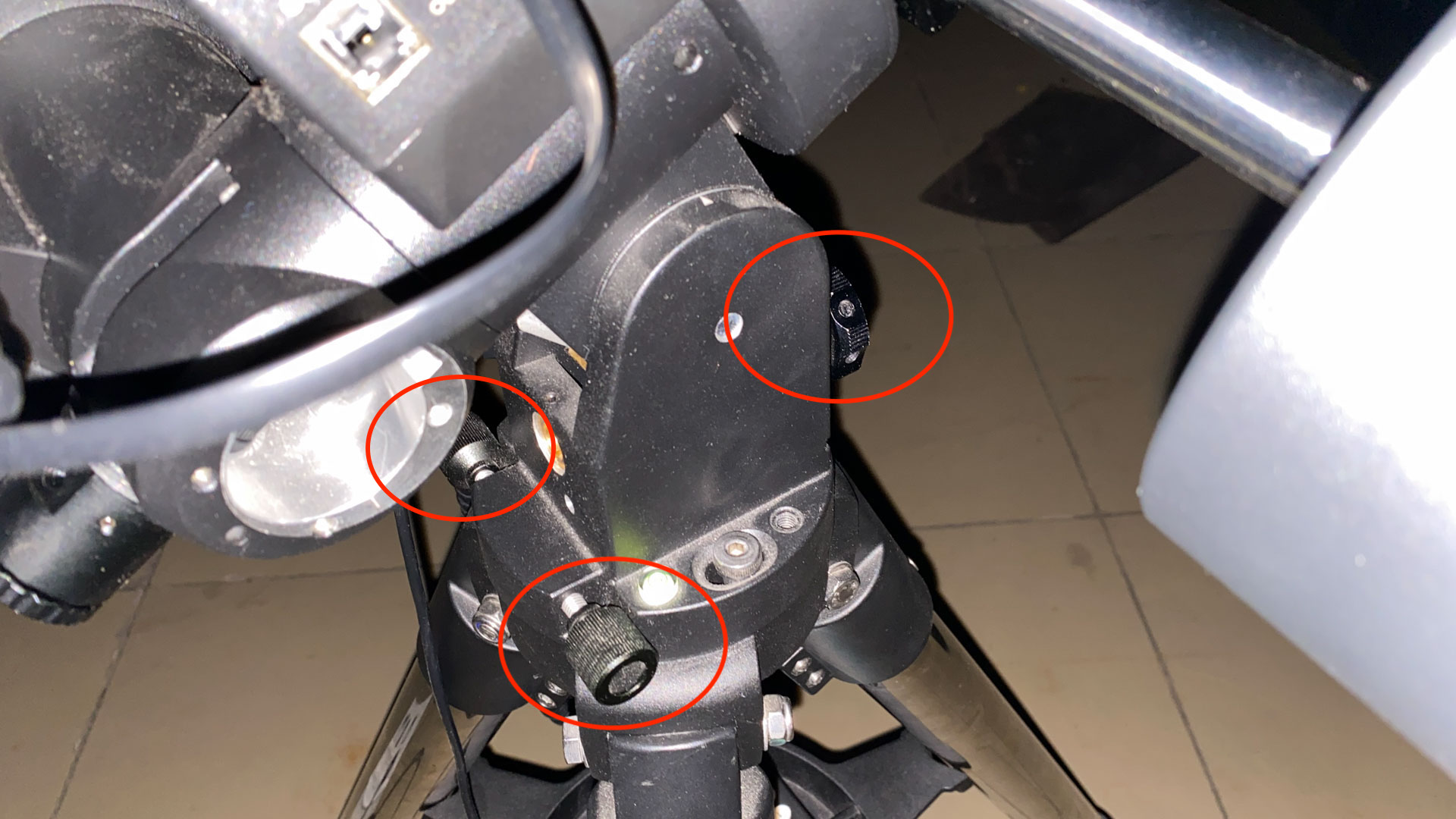
While shining the light indirectly through the front of the scope so that both Polaris and the markings on the dial are visible, you will need to adjust the mount to bring Polaris to the position shown on the dial. For fine horizontal adjustments, use the 2 knobs on the sides of the latitude section, as shown in the photo below, and for fine vertical adjustments, use the same knob in front that is used for fine latitude adjustment.
Use your best estimate to keep the crosshairs perfectly horizontal and vertical instead of tilted, while performing the alignment, and bring polaris to the exact position shown (angle in hrs:mins, and radius). Keep in mind that the target coordinates also slowly change over time, refer back to the controller if you took very long.
Once the tripod mount is aligned, press BACK or MENU on the controller to exit the polaris alignment screen. You don’t need to save any info. Also turn the OTA back to the vertical position and lock the RA axis on the mount. You do not need to unlock any of the mount parts again till dismantling the setup.
Precise Star Alignment
With the observing site data and polar alignment, the mount should already be able to navigate to any given coordinate or object in the sky. However there are usually errors, and we improve the accuracy by performing precise alignment with 1, 2, or upto 3 stars. Three star alignment provides the most accuracy, but also requires more effort. The procedure is the same as for 1 star but repeated 3 times with 3 different stars.
To perform star alignment, you will need to look through the main telescope, so insert an eyepiece, remove the tube lid and bring it to focus on the stars.
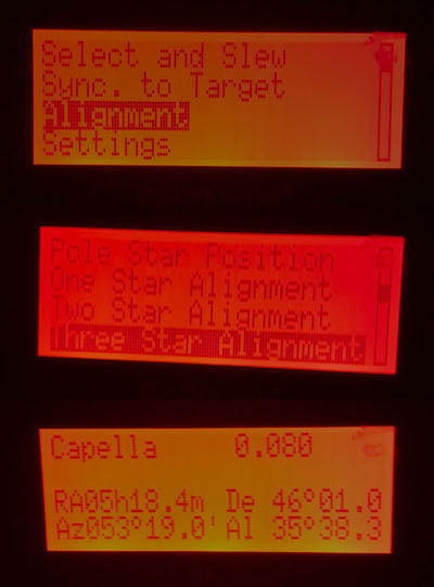
From the controller menu, enter Alignment > Three Star Alignment (or also One/Two star).
There is a list of named bright stars (E.g.- Vega, Sirius, Arcturus, Achernar, Dubhe, etc) and their coordinates and magnitudes. Scroll through the list using the Up/Down arrow keys and select one star that is currently clearly visible in the sky by pressing ENTER, and it will automatically slew to point at the star.
Check the eyepiece to verify whether the same star is visible and centered in the view. If not, bring it to the exact centre of the view by using the 4 arrow keys on the controller to move the RA/Dec axes. You can adjust the slew speed by pressing any of the numbers 1-9 on the keypad. 1 corresponds to the slowest speed (1x, or natural tracking speed), and 9 to the MAX speed, doubling as 2x, 4x, 8x, etc.
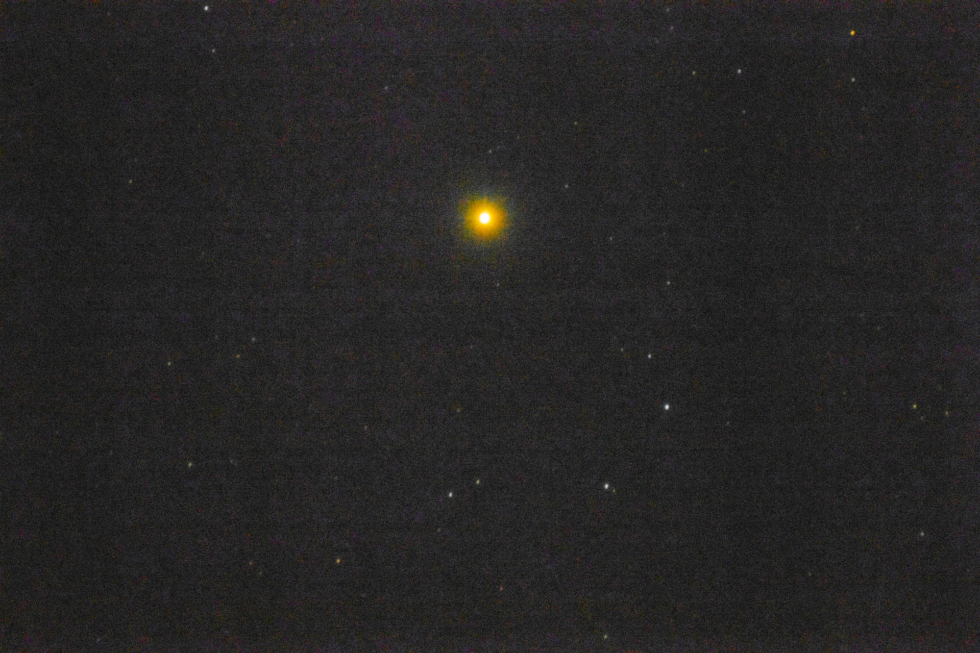
You must be sure that the star visible in the eyepiece is the correct one, else the alignment will be spoilt by submitting wrong info to the computer. You can use a laser to verify where the telescope is pointing, as described in Polar Alignment. Typically, all the stars listed (especially < mag 1), are unmistakably bright in the eyepiece (for example, the image below is of Antares, mag 1.09). Press ENTER to confirm when the star is centered in view.
For 2 or 3 star alignment, it will return to the list of stars and you will have to choose another one and repeat the procedure. When the alignment is complete for all the stars, it will display the message Alignment Accepted and some statistics about the original error that was present. Press BACK or MENU to exit.
Tips for Star Alignment:
- Don’t press
BACKorMENUbefore the alignment is complete or the procedure will be scrapped and you will have to start all over again, for all 1/2/3 stars. Also don’t pressENTERbefore bringing the star to the correct position, since you can’t undo the wrong submission, you will have to cancel and start again. - Use a wide-field eyepiece (e.g. 32mm) to make it easier to spot the stars
- Prefer stars that are spread further across the sky, not near each other in the same constellation, and for 3 star alignment prefer that they are not collinear but form a large triangle, this will help in correcting the alignment error.
Tracking Celestial Objects
You are now ready to view any target in the night sky using the setup. From the controller menu, go to Select and Slew, in which there are many sub-categories of objects in the database - Solar System Planets, Named Stars (like those used for the star alignment), deep-sky catalogs (Messier, NGC, IC), Comets, etc. You can also directly enter RA/Dec coordinates to slew to an arbitrary position.
To go to a specific object, use the arrow keys and navigate through the menus. For catalogs, use the keypad to enter the catalog number (Mxxx, NGCxxxx, etc). Press ENTER to slew to this object. The controller will display Slew in a corner of the LCD display while the telescope is still moving, make a beep sound when it reaches and then display Track to indicate that it is automatically tracking the target. It will keep tracking until you slew to another position, so you can go back and explore the rest of the menus.
While tracking, you can use the arrow keys and keypad to adjust the target position, as in the Star Alignment.
It’s a good idea to first check the accuracy of the alignment by slewing to an easily recognizable object (E.g. Jupiter, The Moon, bright stars, etc) and verifying that it appears in a wide-field (e.g. 32mm) eyepiece before using a higher magnification eyepiece, to get an idea of whether you will need to make a small position adjustment.
The process for connecting a camera, autoguider and imaging is explained in Part 2.
Dismantling
When the observing session is complete,
- Disconnect the main camera, guide camera and their cables from Part 2, if used.
- From the controller menu, first
GoTo Zero Position. - Then ower off the mount using the switch, and the main AC source.
- Then remove the power, controller and RJ45 cables.
- Replace all the caps of the Telecope tube, Finder Scope, Polar Scope, etc
- Remove the OTA from the dovetail slider and pack it carefully.
- Then remove the counterweights and counterweight rod. (Don’t unlock the axes and remove this before the OTA or it will swing over and the tube will crash into the tripod. You don’t need to unlock the mount axes anyway.)
- Remove the accessory tray from the tripod.
- Finally remove the mount head from the tripod if necessary, and pack it carefully.
When packing the components for transportation, remember to
- Use a sturdy, closeable box. Warning: Cardboard can get soggy after absorbing dew/humidity after being left out overnight, and will easily tear under the components’ weight.
- The most valuable and fragile parts are the main telescope tube, the motorized mount head (separate from the tripod), the CMOS guide camera and DSLR/main camera. Use foam/wrap packing in the box for each of these individually.
- Make sure that eyepiece etc lids are closed.
- Pack the counterweight so that it doesn’t slide around in the box/bag and damage the other equipment.